Combined Flow and Deformation Measurements of FSI-Induced Oscillation of a Bluff Flexible Structures in Uniform Flows
Sample Data Plots
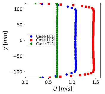
The plot below shows the inlet velocity profiles for the three cases, at \(x=-55\) mm.
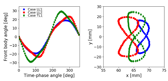
The plots below show the time-phase trace of the angle of the front body of the models through an oscillation period (left), and the path mapped out by the trailing edge coordinates during an oscillation (right), for all three cases.
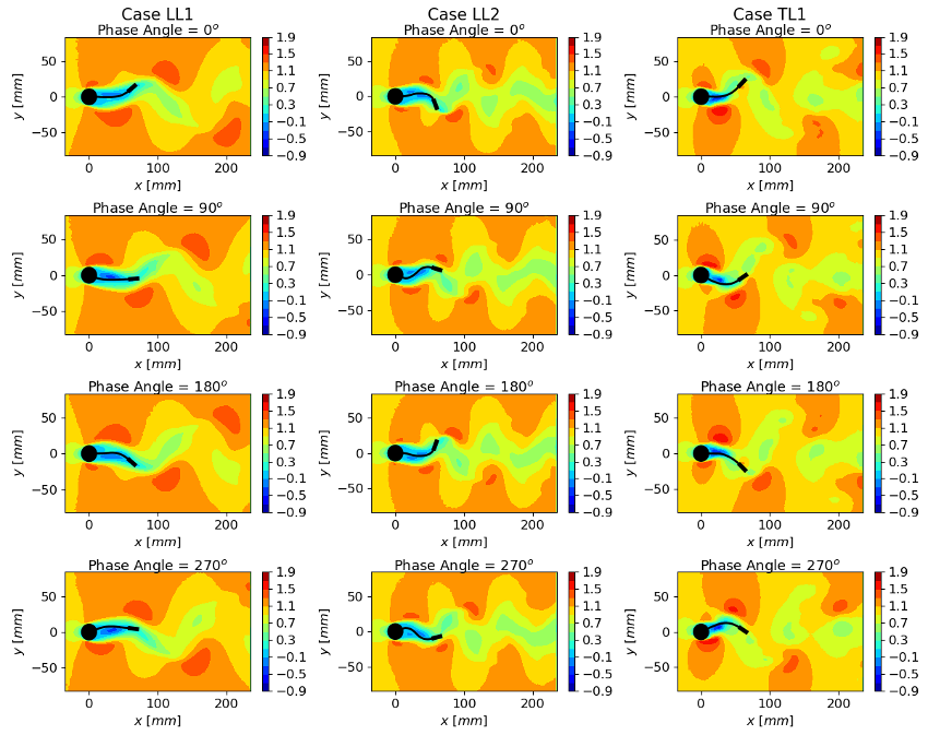
The plots below show contours of the mean \(U\) velocity, and the deformed flexible structure, at selected phase angles for all three cases.


