Table of Contents
Wing/Body Junction with Separation
Experiments by Devenport, Simpson and Fleming
Description
Turbulent flow at the junction of a flat surface and a normally-mounted cylindrical wing dominated by the presence of a horseshoe vortex. 3D flow with constant temperature.
Geometry
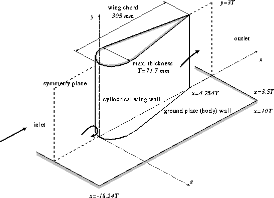
The cylindrical wing has a maximum thickness of \(T = 71.7\) mm and a chord length of 305 mm. It is situated \(18.24T\) downstream from the inlet and has its chord aligned with the \(x\) axis. Its cross-section consists of a 3:2 elliptical nose (major axis aligned with the chord) and NACA 0020 tail joined at the maximum thickness (see figure 1).
Flow Characteristics
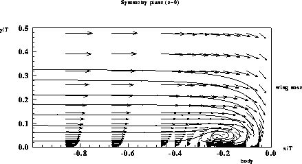
The adverse pressure gradient in the plane of symmetry causes the boundary layer approaching the wing to separate. Upstream of separation, and in the vicinity of the separation point, mean velocity and Reynolds stress profiles are like those in a 2D boundary layer separating in an adverse pressure gradient. The junction vortex is observed as an intense approximately elliptical recirculation zone in this plane, centred about one-tenth of the undisturbed boundary-layer thickness from the wall (see figure 2). This zone also appears as a region of intense turbulence production resulting from the large-scale unsteadiness of the flow. This unsteadiness is characterized by a bimodal velocity probability density function. According to the authors this feature is likely to make turbulence models assuming a Gaussian shape of the velocity pdf perform poorly in this region.
 Fig. 2: Flow pattern on the symmetry plane upstream of the wing leading edge
Flow Parameters
The conditions corresponding to the studies of Devenport & Simpson (1990) and Fleming et al (1993) are:
- Air at temperature 25oC and pressure 94500 Pa.
- Reference velocity: \(U_{ref} = 26.75\) m/s.
Inflow Conditions
At \(x/T = -18.24\), the following measurements are provided in wbj-etab1.dat for the two-dimensional boundary-layer which has developed under zero pressure gradient conditions after being tripped:
- Profiles at \(z = 0\) for \(y/T\) ranging from 0 to 0.87 of first order moment: \(U/U_{ref}\), and second order moments: \(\overline{u^2}/U_{ref}^2\), \(\overline{w^2}/U_{ref}^2\), \(\overline{uw}/U_{ref}^2\)
The boundary layer conditions quoted in Fleming et al (1993) for the incoming flow (at \(x/T=-2.146\)) in a number of studies of the same flow geometry are given in the table below. Elements of measurement data from all these studies are provided below.
| Data Set | JLF, WJD1 | WJD2 | SCD | HMM | JS |
|---|---|---|---|---|---|
| \(T\) (cm) | 7.17 | 7.17 | 6.1 | 7.1 | 7.1 |
| \(U_{ref}\) (m/s) | 26.75 | 32.0 | 30.5 | 15.24 | 20.9 |
| \(\delta/T\) | 0.513 | 0.263 | 1.197 | 0.947 | 1.15 |
| \(\delta^*/T\) | 0.0779 | 0.043 | 0.1345 | 0.1467 | 0.148 |
| \(\theta/T\) | 0.0548 | 0.031 | 0.1014 | 0.1003 | 0.1227 |
| \(C_f\) | 0.00247 | 0.0028 | 0.00247 | 0.00232 | 0.00256 |
| \(Re_{\theta}\) | 6300 | 4500 | 11600 | 6800 | 11700 |
Inlet boundary conditions for a number of wing/body junction studies. JLF: Fleming et al (1991), Fleming et al (1993); WJD1: Devenport & Simpson (1990); WJD2: Devenport et al (1990): SCD: Dickinson (1986) HMM: McMahon et al (1987); JS: Shin (1989)
Experimental Details
Ground plate and wing wall static pressure measurements by Devenport and Simpson (WJD) through 1 mm tappings. \(C_p\) is defined as \((p - p_{ref})/(p_o - p_{ref})\) where \(p_o\) and \(p_{ref}\) are respectively the stagnation and static pressures of the undisturbed free stream.
Velocity measurements by Fleming (JLF) using a boundary-layer type single-hot-wire probe.
Velocity measurements by Devenport and Simpson (WJD) using an argon-ion LDV system.
Measurement Errors:
Uncertainty in wall static pressure measurements and LDV velocity measurements (by WJD):
| \(\delta(C_p)\) | \( \pm 0.005\) |
|---|---|
| \(\delta(U/U_{ref})\) | \( \pm 0.025\) |
| \(\delta(\overline{u^2}/U_{ref}^2)\) | \( \pm 0.0016\) |
| \(\delta(\overline{uv}/U_{ref}^2)\) | \( \pm 0.0019\) |
Uncertainty in single-hot-wire velocity measurements (by JLF):
| \(\delta(U/U_{ref})\) | \( \pm 1.5\% \) |
|---|---|
| \(\delta(W/U_{ref})\) | \( \pm 3.0\% \) |
| \(\delta(u'/U_{ref})\) | \( \pm 1.5\% \) |
| \(\delta(w'/U_{ref})\) | \( \pm 5.0\% \) |
| \(\delta(|\overline{uw}|^{1/2}/U_{ref})\) | \( \pm 5.0\% \) |
Available Measurements
The data can be downloaded as compressed archive files from the links below, or as individual files by selecting those required from the tables.
Sample plots of selected quantities are available.
Velocity measurements
- Measurements in the symmetry plane upstream of the wing, consisting of profiles at 11 \(x\) locations of:
- First order moments, \(U/U_{ref}\), \(V/U_{ref}\)
- Second order moments: \(\overline{u^2}/U_{ref}^2\), \(\overline{v^2}/U_{ref}^2\), \(\overline{uv}/U_{ref}^2\)
- Skewness and Kurtosis
| \(x/T=-0.05\) | wbj-el01tc.dat |
|---|---|
| \(x/T=-0.104\) | wbj-el02tc.dat |
| \(x/T=-0.1537\) | wbj-el03tc.dat |
| \(x/T=-0.2036\) | wbj-el04tc.dat |
| \(x/T=-0.251\) | wbj-el05tc.dat |
| \(x/T=-0.3\) | wbj-el06tc.dat |
| \(x/T=-0.3513\) | wbj-el07tc.dat |
| \(x/T=-0.404\) | wbj-el08tc.dat |
| \(x/T=-0.461\) | wbj-el09tc.dat |
| \(x/T=-0.667\) | wbj-el10tc.dat |
| \(x/T=-0.86\) | wbj-el11tc.dat |
- Measurements in a number of \(y - z\) planes corresponding to different streamwise locations \(x/C\). The table below shows availability and components measured. Data extracted by Fleming from the studies of Dickinson (1986), McMahon et al (1987) and Shin (1989) are also included. In the case of the SCD and HMM datasets, files with names ending in 'i' are also provided, in which the data was linearly interpolated to match the \(z/T\) locations of the JLF data, for ease of comparison.
| plane number | \(x/C\) | JLF | WJD | WJD2 | SCD | HMM | JS |
|---|---|---|---|---|---|---|---|
| 05 | 0.18 | wbj-fp05tc.dat \(U, W, u', w', \overline{uw}\) | wbj-lp05tc.dat \(U, V, W, u', v', w', \overline{uv}, \overline{uw}\) | wbj-dp05tc.dat \(U, V, W, u', v', w', \overline{uv}, \overline{uw}\) wbj-dp05tci.dat | wbj-sp05tc.dat \(U, V, W\) |
||
| 06 | 0.42 | wbj-fp06tc.dat \(U, W, u', w', \overline{uw}\) | wbj-sp06tc.dat \(U, V, W\) |
||||
| 07 | 0.64 | wbj-fp07tc.dat \(U, W, u', w', \overline{uw}\) | wbj-dp07tc.dat \(U, V, W, u', v', w', \overline{uv}, \overline{uw}\) wbj-dp07tci.dat | ||||
| 08 | 0.75 | wbj-lp08tc.dat \(U, V, W, u', v', w', \overline{uv}, \overline{uw}\) | wbj-dp08tc.dat \(U, V, W, u', v', w', \overline{uv}, \overline{uw}\) wbj-dp08tci.dat | wbj-mp08tc.dat \(U, V, W, u', v', w', \overline{uv}, \overline{uw}, \overline{vw}\) wbj-mp08tci.dat | |||
| 09 | 0.93 | wbj-fp09tc.dat \(U, W, u', w', \overline{uw}\) | wbj-dp09tc.dat \(U, V, W, u', v', w', \overline{uv}, \overline{uw}\) wbj-dp09tci.dat | ||||
| 10 | 1.05 | wbj-fp10tc.dat \(U, W, u', w', \overline{uw}\) | wbj-lp10tc.dat \(U, V, W, u', v', w', \overline{uv}, \overline{uw}\) | wbj-dp10tc.dat \(U, V, W, u', v', w', \overline{uv}, \overline{uw}\) wbj-dp10tci.dat | wbj-mp10tc.dat \(U, V, W, u', v', w', \overline{uv}, \overline{uw}, \overline{vw}\) wbj-mp10tci.dat | wbj-sp10tc.dat \(U, V, W\) |
|
| 11 | 1.5 | wbj-fp11tc.dat \(U, W, u', w', \overline{uw}\) | wbj-dp11tc.dat \(U, V, W, u', v', w', \overline{uv}, \overline{uw}\) wbj-dp11tci.dat | ||||
| 12 | 3.0 | wbj-lp12c.dat \(U, u'\) | wbj-lp12tcs.dat \(U, u'\) | wbj-mp12tc.dat \(U, V, W, u', v', w', \overline{uv}, \overline{uw}, \overline{vw}\) wbj-mp12tci.dat | |||
| 13 | 5.89 | wbj-fp13c.dat \(U, u'\) | |||||
| 14 | 9.14 | wbj-fp14c.dat \(U, u'\) | |||||
| 15 | 11.56 | wbj-fp15c.dat \(U, u'\) |
Pressure measurements
Several pressure coefficient, \(C_p\), profiles are available for three free-stream velocity case:
- Profiles of \(C_p\) around the wing wall for \(y/T=0.133\), \( 0.398\), \(1.46\) and \(1.73\).
- Profiles of \(C_p\) on the ground plate from \(z/T=-1.5\) to \(1.5\) at several \(x\) locations ranging from \(x/T=-2\) to \(4.75\).
- Profiles of \(C_p\) on the ground plate at \(z/T=\pm 3.18\) from \(x/T=-2\) to \(4.9\)
| \(U_{ref}\) [m/s] | Wing-wall \(C_p\) | Ground plate \(C_p\) | Ground plate \(C_p\) at \(z/T=\pm 3.18\) |
|---|---|---|---|
| 8 | wbj-cp-wing-8.dat | wbj-cp-body-8.dat | wbj-cp-body-zpm-8.dat |
| 16.5 | wbj-cp-wing-16.dat | wbj-cp-body-16.dat | wbj-cp-body-zpm-16.dat |
| 27.6 | wbj-cp-wing-27.dat | wbj-cp-body-27.dat | wbj-cp-body-zpm-27.dat |
Recommendations for Calculations
The following suggestions were given to contributors to a collaborative workshop in which the case was studied.
Inlet Conditions: The calculation of the boundary layer should be started at \(x/T\ = -18.24\) using the experimental values provided as inlet conditions. Assume that the non-measured quantities \(V\) and \(W\) are negligible as expected in a 2D boundary layer. On the other hand \(\overline{v^2}\) can be estimated as \(2\overline{w^2} - \overline{u^2}\).
Symmetry: Due to geometric symmetry with respect to the \(z = 0\) plane - the plane containing the chord of the wing - one can use a computational domain including only one half of the wing.
Outlet Conditions: The outlet should be placed sufficiently far away, typically \(x \ge 10T\), so that the vortex is developed and the boundary layer recovers its two-dimensionality. Zero gradients may then be assumed for the flow variables.
Boundary Parallel to the Ground Plate Wall: This boundary should be placed at \(y \ge 3T\) typically.
Boundary Parallel to the Symmetry Plane: This boundary should be placed sufficiently far away, typically \(z \ge 3.5T\).
Main References
- Devenport, W.J., Simpson, R.L. (1990). Time-dependent and time-averaged turbulence structure near the nose of a wing-body junction. J. Fluid Mech. Vol. 210, pp. 23-55.
- Fleming, J.L., Simpson, R.L., Cowling, J.E., Devenport, W.J. (1993). An experimental study of a turbulent wing-body junction and wake flow. Experiments in Fluids, Vol. 14, p. 366.
- Devenport, W.J., Agarwal, N.K., Dewitz, M.B., Simpson, R.L., Poddar, K. (1990). Effects of a fillet on the flow past a wing-body junction. AIAA J., Vol. 28, pp. 2017-2024.
- Fleming, J.L., Simpson, R.L., Devenport, W.J. (1991). An experimental study of a turbulent wing-body junction and wake flow, Virginia Polytechnic Institute Technical Report VPI-AOE-179.
- Dickinson, S.C. (1986). An experimental investigation of appendage-flat plate junction flow, vol 1: description. DTNSRDC-86/051.
- Dickinson, S.C. (1986). An experimental investigation of appendage-flat plate junction flow, vol 2: . DTNSRDC-elliptical nose appendage data base. DTNSRDC-86/052.
- McMahn, H.M., Merati, P., Yoo, K.M. (1987). Mean velocities and Reynolds stresses in the juncture flow and in the shear layer downstream of an appendage. GITAER 87-4, Georgia Institute of Technology.
- Shin, J. (1989). Effective methods of controlling a junction vortex system in incompressible, three-dimensional, turbulent flow. PhD Dissertation, Virginia Polytechnic Institute and State University.
Indexed data:
| case008 (dbcase, flow_around_body, semi_confined_flow) | |
|---|---|
| case | 008 |
| title | Wing-Body Junction with Separation |
| author | Devenport, Fleming, Simpson |
| year | 1988 |
| type | EXP |
| flow_tag | 3d, surface_mounted_body |
