Table of Contents
Turbulent Boundary Layer Flow Over a Cube
Wind tunnel experiments by Lim, Castro and Hoxey
Flow Configuration
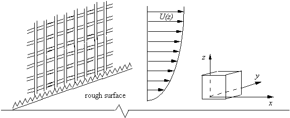
Field experiments at Silsoe Research Institute and experiments in two wind tunnels at the University of Southampton (called 'ST' and 'LT' below) were performed. The general tunnel arrangement is shown in figure 1, with flow from left to right. In each tunnel a 'partial depth' neutrally stable atmospheric boundary simulation was created (Cook, 1978) using the hardware sketched in the figure: a mixing grid, a castellated fence and a rough surface (expanded mesh). The details of this are unimportant here. Data users wishing to compute the cube flow need merely to ensure that their upstream boundary layer has characteristics matching those measured (see below), which were designed to be similar to the neutrally stable atmospheric boundary layer measured at the field site.
Geometrical and Flow Parameters
Geometrical Parameters
- Cube height: \(h=80\) mm and \(240\) mm (small and large tunnels).
- Tunnel cross-section (width x height): 0.9 x 0.6 m (small) and 3.4 x 2.5 m (large).
- In the field, \(h=6\) m; the cube was located in an unobstructed rural site.
Flow Parameters
- Reynolds number range: \(1.86 \times 10^4 < U_h h/\nu < 40.6 \times 10^4\), where \(\nu = 15 \times 10^{-6}\) m2/s, and \(U_h\) is the velocity in the undisturbed boundary layer at height \(z=h\).
- Roughness length, \(z_o = 0.09\) mm and \(0.35\) mm (small and large tunnels) and \(8\) mm in the field.
The developed mean velocity and turbulence Reynolds stress profiles at the eventual cube location, but in its absence, were obtained using combinations of Hot Wire, Laser Doppler and (in the field) ultrasonic anemometry.
Details of all techniques are given by Castro et al. (2006).
Available Data
Available data includes:
- Boundary layer profiles of mean velocity and Reynolds stresses in the two wind tunnels
- Surface mean and rms fluctuating pressure coefficients across the top of the cube (for the case of the cube normal to the flow, and at 45o to it
- Mean velocity and Reynolds stress measured just above the top surface of the cube
Measurements are provided for a range of Reynolds numbers, although in most cases the dependence on the Reynolds number is not very strong.
Sample plots of selected quantities are available.
The data files can be downloaded as compressed archives, or individually from the tables below.
Boundary layer profiles. Profiles of mean velocity and Reynolds stresses in the undisturbed boundary layer, for a range of inlet velocities.
Cube Normal to Approach Flow
| Top Surface Pressure Coefficients | |||
|---|---|---|---|
| Location | Mean \(C_p\) | Rms \(C_p'\) | |
| Axial centreline, \(y/h=0\) | cp0a.dat | cpp0a.dat | Data from large and small tunnels, and field, for various inlet velocities |
| Transverse centreline, \(x/h=0.5\) | cp0t.dat | cpp0t.dat | Data from large and small tunnels, for various inlet velocities |
| Near-Top-Surface Velocity | |||
| Location | Mean \(U\) and rms \(u'\) | ||
| Axial centreline, \(y/h=0\) | veltop.dat | Data from large and small tunnels, and field, for various inlet velocities | |
Cube at \(45^o\) to Approach Flow
| Top Surface Pressure Coefficients | |||
|---|---|---|---|
| Location | Mean \(C_p\) | Rms \(C_p'\) | |
| Axial diagonal, \(y/h=0\) | cp45a.dat | cpp45a.dat | Data from large and small tunnels, and field, for various inlet velocities |
| Near front edge | cp45e.dat | Data from large and small tunnels, for various inlet velocities | |
| Transverse diagonal, \(x/h=0.707\) | cpp45t.dat | Data from large and small tunnels, for various inlet velocities | |
Related Publications
- Castro, I.P., Robins, A.G. (1977). The flow around a surface mounted cube in uniform and turbulent streams. J. Fluid Mech., Vol. 79, pp. 307-355.
- Cook, N. (1978). Wind tunnel simulation of the adiabatic atmospheric boundary layer by roughness, barrier and mixing device methods. J. Wind Eng. Ind. Aero., Vol. 3, pp. 157-176.
- Hoxey, R.P., Reynolds, A.M., Richards, G.M., Robertson, A.P., Short, J.L. (1998). Observations of Reynolds number sensitivity in the separated flow region on a bluff body. J. Wind Eng. Ind. Aero., Vol. 73, pp. 231-249.
- Lim, H.C., Castro, I.P., Hoxey, R.P. (2006). Bluff bodies in deep turbulent boundary layers: Reynolds number issues. J. Fluid Mech., Vol. 71, pp. 97-118.
Indexed data:
| case084 (dbcase, flow_around_body, semi_confined_flow) | |
|---|---|
| case | 084 |
| title | Turbulent boundary layer over a cube |
| author | Lim, Castro, Hoxey |
| year | 2006 |
| type | EXP |
| flow_tag | 3d, separated, surface_mounted_body |
