Swirling and Non-Swirling Flows in Curved Pipe
Experiments by Anwer and So
Description
Swirling and non-swirling flows in a circular cross section pipe made of a 180o bend and two long straight inlet and outlet parts. 3D flow with constant temperature.
Geometry of the Computational Domain
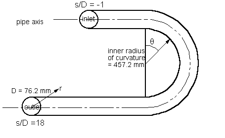
A circular pipe with two straight and one curved parts (see figure 1).
Circular cross-section of the pipe: diameter \(D = 2a = 76.2\) mm.
Inner radius of curvature of the bend: 457.2 mm.
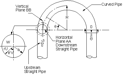
Mean radius of curvature of the bend: \(R = 495.3\) mm.
Both straight inlet and outlet parts are \(96D\) long. For CFD simulations it is recommended that the inlet be placed at least \(1D\) upstream of the curved section.
The coordinate \(s\) is defined along the centreline of the straight parts of the pipe (with \(s<0\) corresponding to upstream of the bend and \(s>0\) to downstream). The angle \(\theta\) is used to determine position around the bend.
In the swirling case a section of pipe rotating about about its axis was introduced in the upstream section between \(s/D=-12\) to \(-6\) in order to generate the swirl.
Flow Characteristics
A Dean-type secondary motion is encountered as expected in the bend, but at \(\theta = 112.5^o\) measurements exhibit a second cell in the secondary flow. This cell disappears at about one diameter downstream from the curved section. It takes a long distance for the viscous dissipation to annihilate the extra turbulence energy produced by the bend curvature and complete recovery is not achieved at the last measuring location (\(s/D = 18\) in the non-swirling case).
Flow Parameters
- Air with a kinematic viscosity: \(\nu = 1.58 \times 10^{-5}\) m2/s.
- Bulk axial velocity in inlet straight pipe: \(W_o = 10.4\) m/s.
- Reynolds number: \(W_oD/\nu = 5 \times 10^5\).
- Wall friction velocity measured at \(s/D = -18\): \(w_{\tau s} = 0.323\) m/s.
- Rotational speed of pipe section (for swirling case): \(\Omega = 272\) rad/s.
- Swirling number: \(N_s = a\Omega/W_o = 1.0\) and \(0\).
Inflow Conditions
For the non-swirling case profiles along the horizontal and vertical radii of the circular cross-section upstream of the bend are provided at \(s/D=-18\) (files beh00-sm18.dat, bev00-sm18.dat) and \(s/D=-1\) (files beh00-sm01.dat and bev00-sm01.dat).
For the swirling case profiles are provided at \(s/D=-4\) (files beh01-sm04.dat, bev01-sm04.dat) and \(s/D=-1\) (files beh01-sm01.dat and bev01-sm01.dat), both locations being downstream of the swirl generating section.
Experimental Details
The curved-pipe rig used in this study consists of two straight Plexiglas pipes connected to a U-bend made from Plexiglas tubing. The pipe has an inside diameter of \(D = 76.2\) mm. Both the upstream and the downstream straight pipes are 7.3 m long, thus giving a length-to-diameter ratio of 96. This length is long enough to ensure a fully developed turbulent pipe flow upstream of the bend entrance. The U-bend has a mean radius \(R\) of 495.3 mm and therefore gives a pipe to bend radius ratio of \(\alpha= 0.077\). Airflow is drawn through the test rig using a centrifugal blower placed at one end of one of the straight pipes. Blower vibration is isolated by allowing a small air gap to exist between the blower and the Plexiglas pipe. The present arrangement has the blower at the exit end of the test rig, thus preventing any blower-generated flow distortions from penetrating into the inlet straight pipe and the curved bend.
The region bounded by \(s/D = \pm 18\) definition of the axes was instrumented with wall pressure taps along two diametrically opposite generators to measure the pressure drop along the straight pipes and the bend. Here, \(s\) denotes the axial co-ordinate along the straight pipes. Experiments were carried out at a pipe Reynolds number of 50000. This corresponds to a \(De\) (\(=Re(a/R)^{1/2}\)) of 13868 and a mean bulk velocity \(W_o\) of 10.4 m/sec. Fully developed turbulent pipe flow condition was checked at \(s/D = -26\) and \(-18\) and the measurements were compared with those of Laufer obtained at the same \(Re\). The flow properties at \(s/D = -18\) were found to be identical to those measured by Laufer. Wall shear measurements were carried out at selected stream locations in the region \(s/D = \pm 18\). For easy comparison with the wall shear results mean and fluctuating velocity measurements were carried out at \(s/D = -18\) and \(-1\) in the upstream straight pipe, at \(\theta = 22.5^o\), \(67.5^o\), \(112.5^o\), and \(157.5^o\) within the bend, and at \(s/D = 1\), \(6\), \(10\), and \(18\) in the downstream straight pipe, where \(\theta\) is the axial angular co-ordinate along the U-bend. Measurements were made along a diameter that lies in the plane of the bend (plane AA) and a radius normal to the plane of the bend (plane BB), see figure 2.
For the swirling case a section of pipe that could be rotated about its axis, 6 diameters long, was installed 6 diameters upstream of the curved bend entrance. It was designed to provide a solid-body rotation to the flow at the exit of the rotating section, as verified by Anwer and So (1989) at two diameters downstream of the rotating section. In this case measured profiles were also taken further downstream, at \(s/D=30\) and \(49\).
Measurement Techniques
- Velocity measurements using a miniature hot-wire probe.
- Shear stress measurements using a hot film sensor and a shear stress gauge.
- Static pressure measurements using wall tappings. The pressure coefficient is defined as \(C_p = (p - p_o)/(0.5\rho W_o^2)\), where \(p_o\) is the static pressure at \(s/D = -18\).
Measurement Errors
- \(\delta(U)/W_o\) : 3%
- \(\delta(\overline{u^2})/w_{\tau s}\) : 4%; \(\delta(\overline{uv})/w_{\tau s}\) : 5%
- \(\delta(V)/W_o\) : 7%
- \(\delta(\overline{v^2})/w_{\tau s}\) : 2%; \(\delta(\overline{uw})/w_{\tau s}\) : 5%
- \(\delta(W)/W_o\) : 0.3%
- \(\delta(\overline{w^2})/w_{\tau s}\) : 5%; \(\delta(\overline{vw})/w_{\tau s}\) : 4%
Available Measurements
Measured data available includes:
- Profiles of mean velocities and Reynolds stresses along horizontal and vertical radii at several locations upstream of the bend, through the bend, and downstream.
- Wall shear stress around the pipe circumference at several locations upstream of the bend, through the bend, and downstream.
- Static pressure around the inner and outer bend wall surfaces.
Sample plots of some of the quantities are available.
The data can be downloaded as compressed archive files from the links below, or as individual files by selecting those required from the tables.
Velocity measurements
The files below give velocity measurements along the vertical and the horizontal radii at selected sections upstream of the bend, through the bend, and downstream in the recovery part. Measured quantities include:
- First order moments: \(W/W_o\), \(V/W_o\), \(U/W_o\)
- Second order moments: \(\overline{u^2}/w_{ts}^2\), \(\overline{v^2}/w_{ts}^2\), \(\overline{w^2}/w_{ts}^2\), \(\overline{uv}/w_{ts}^2\), \(\overline{uw}/w_{ts}^2\), \(\overline{vw}/w_{ts}^2\)
Note that \(W\) corresponds to the axial velocity component, \(V\) to the circumferential component, and \(U\) to the radial component.
| Non-Swirling Case | ||
|---|---|---|
| Horizontal Plane | Vertical Plane | |
| \(s/D=-18\) | beh00-sm18.dat | bev00-sm18.dat |
| \(s/D=-1\) | beh00-sm01.dat | bev00-sm01.dat |
| \(\theta=22.5^o\) | beh00-th0225.dat | bev00-th0225.dat |
| \(\theta=67.5^o\) | beh00-th0675.dat | bev00-th0675.dat |
| \(\theta=112.5^o\) | beh00-th1125.dat | bev00-th1125.dat |
| \(\theta=157.5^o\) | beh00-th1575.dat | bev00-th1575.dat |
| \(s/D=1\) | beh00-sp01.dat | bev00-sp01.dat |
| \(s/D=6\) | beh00-sp06.dat | bev00-sp06.dat |
| \(s/D=10\) | beh00-sp10.dat | bev00-sp10.dat |
| \(s/D=18\) | beh00-sp18.dat | bev00-sp18.dat |
| Swirling Case | ||
|---|---|---|
| Horizontal Plane | Vertical Plane | |
| \(s/D=-4\) | beh01-sm04.dat | bev01-sm04.dat |
| \(s/D=-1\) | beh01-sm01.dat | bev01-sm01.dat |
| \(\theta=22.5^o\) | beh01-th0225.dat | bev01-th0225.dat |
| \(\theta=67.5^o\) | beh01-th0675.dat | bev01-th0675.dat |
| \(\theta=112.5^o\) | beh01-th1125.dat | bev01-th1125.dat |
| \(\theta=157.5^o\) | beh01-th1575.dat | bev01-th1575.dat |
| \(s/D=1\) | beh01-sp01.dat | bev01-sp01.dat |
| \(s/D=6\) | beh01-sp06.dat | bev01-sp06.dat |
| \(s/D=10\) | beh01-sp10.dat | bev01-sp10.dat |
| \(s/D=18\) | beh01-sp18.dat | bev01-sp18.dat |
| \(s/D=30\) | beh01-sp30.dat | bev01-sp30.dat |
| \(s/D=49\) | beh01-sp49.dat | bev01-sp49.dat |
Wall Shear Stress Measurements
Wall friction coefficient distribution around the pipe circumference at selected locations upstream of the bend, through the bend, and downstream.
| Non-Swirling Case | Swirling Case |
|---|---|
| bshr00.dat | bshr01.dat |
Pressure Measurements
Distribution of the static pressure coefficient, \(C_p\), around the outer and inner bend surfaces.
| Non-Swirling Case | Swirling Case |
|---|---|
| pres00.dat | pres01.dat |
Main References
- Anwer, M. (1989). Rotating turbulent flow through a 180 degree bend. PhD thesis, Arizona State University.
- Anwer, M., So, R.M.C. (1989). Rotation effects on a fully developed turbulent pipe flow. Exp. Fluids, Vol. 8, pp. 33-40.
- Anwer, M., So, R.M.C., Lai, Y.G. (1989). Perturbation by and recovery from bend curvature of a fully developed turbulent pipe flow. Phys. Fluids A: Fluid Dynamics, Vol. 1, pp. 1387-1397.
- Anwer, M., So, R.M.C. (1993). Swirling turbulent flow through a curved pipe. Part 1: Effect of swirl and bend curvature. Exp. Fluids, Vol. 14, pp. 85-96.
- So, R.M.C., Anwer, M. (1993). Swirling turbulent flow through a curved pipe. Part 2: Recovery from swirl and bend curvature. Exp. Fluids, Vol. 14, pp. 169-177.
Indexed data:
| case004 (dbcase, confined_flow) | |
|---|---|
| case | 004 |
| title | Swirling and Non-Swirling Flows in Curved Pipe |
| author | Anwer, So |
| year | 1989 |
| type | EXP |
| flow_tag | 3d, swirl, curvature, constant_cross_section |

