Near-Wake Flow of a V-gutter with Slit Bleed
Experiments by Yang and Tsai
Description
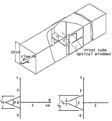
The cold-flow characteristics of a v-shape flame holder with flow bleed from a slit located at the leading edge (as shown in figure 1) have been investigated. A nonsymmetric wake structure is developed behind the symmetric slit v-gutter. The flow through the slit induces greater reverse flow and greater back pressure in the near wake. It also provokes more extensive transport across the shear layers and reduces both the turbulent intensity and the Reynolds shear stress of the wake flow. These results indicate that the slit v-gutter can have a better flame holding ability and less pressure loss compared with the traditional v-gutter.
Experimental Details
Test Rig
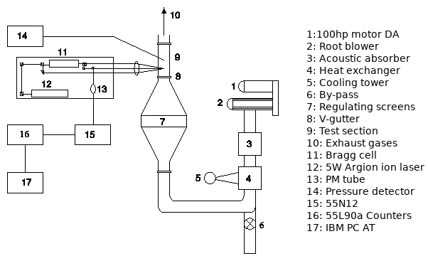
The full test rig is shown schematically in figure 2. The experiments were conducted in an open-circuit wind tunnel blown by a 75 kw Roots blower, the speed of which was controlled by means of a frequency inverter. The blower provided a maximum flow rate 50 m3/min with a maximum static pressure 70 kPa. The dimension of the test section was 10 x 10 cm2. The configurations of the two types of v-gutter tested are shown in figure 1. The flow structures were investigated quantitatively through the measurements of velocities and pressures.
Instrumentation
The velocities were measured with a Dantec three-beam, 2-component backward-scattering LDA, connected to a computer-controlled traversing system for two-dimensional movement. The resolution of the traverse system was 0.03 mm.
The instruments were mounted on an optical bench that was placed on a mill table for major movement. The laser beam from a 5-watt argon-ion laser emitting mainly at wavelengths 514.5 and 488 nm was split into two beams.
One beam passed a Bragg cell to produce a 40-MHz frequency shift and was then split again, through a colour-selective beam splitter, into two beams of wavelengths 514.5 and 488 nm.
The resulting two beams and the other original beam passed a beam translator, a beam expander and a convergent lens of focal length 310 mm, and were focused at the desired position. The two axes of the blue beam of the optical probe were 0.128 and 1.625 mm, whereas those of the green beam were 0.135 and 1.713 mm.
The backward-scattering Doppler signals were detected by two photomultipliers and processed by a coincidence filter and two counter processors. A beam waist adjustor was used before the whole optical system in order to improve the signals. The seeding particles were generated from a seeding generator (Dantec) and heated and then introduced into the stream of flowing air at the divergent section of the wind tunnel. The particles, with a diameter of the order of 1 mm were made of 25 percent glycerin resolvent and a water solvent. The measurements of pressure were made through a 1.5 mm-o.d. L-shaped tube with eight 0.1 mm holes drilled around the end of the tube.
The mean pressures were measured by a traversing miniature pitot tube every 2 millimetres across the transverse direction and every 5 millimetres along the axial direction the recirculation zone.
Experimental Conditions
V-gutters of two types, regular and irregular, were tested. Those of irregular type had an open slit at the leading edge. Sketches of the configuration and co-ordinate system of the test section and the v-gutters are shown in figure 1. The span angle of the v-gutter was 45 degrees, corresponding to a blockage ratio 0.20. The range of the flow velocities was 1-20 m/s, corresponding to Reynolds numbers (\(U_{o}L_b/\nu\)) of \(1.2 \times 10^3\) - \(2.4 \times 10^4\) where \(L_b\) is the width at the end of the v-gutters. In order to obtain better images, the tests of flow visualisation were conducted at a flow velocity of 1 m/s. The turbulent intensity in front of the v-gutter was less than 0.85 percent. The widths of the open-slit (\(L_s\)) of the irregular v-gutter were chosen to be 2 mm and 4 mm, respectively.
Measurement Errors
For statistical analysis, the mean values of 30,720 samples of velocity measurements near the rear- stagnation point (the variation of the mean velocity was less than 0.1 m/s at \(U_o = 20\) m/s) were chosen as the “accurate” reference values. Since the measuring time for 30,720 data samples near the rear-stagnation point would consume 150 minutes, only 2048 measurements were typically made at each measuring point. The corresponding maximum uncertainties were 3.2 percent of the mean axial velocity, 4.9 percent of the mean transverse velocity, and 4.9 percent of the turbulent intensity at the 95 percent confidence level. In the mean time, the axial velocities were integrated along each cross section to obtain the mass flow rate. The results showed that the mass flow rates of all of the test sections normalised by the flow rate of upstream were between 0.95 and 1.05. The corresponding maximum uncertainty of the Reynolds shear stress was 13 percent.
The spanwise uniformity of the wake flow (\(U\), \(V\), \(u'\), \(v'\)) was examined behind the 2-mm open slit v-gutter at \(x = 20\) mm and \(y = 10\) mm. The location was near the centre of the upper shear layer and the flow there was highly turbulent and likely to be three-dimensional. The results show that the distribution along the spanwise direction was almost constant and the three-dimensional effects were negligible in the experimental results.
More than 20,000 data were taken for each point of pressure measurement; the sampling period was 500µs. The uncertainty of the pressure measurement was calculated by systematically changing the revolution of instruments, recording 20 sets of data and then conducting a statistical analysis of deviations. The uncertainty of the pressure data was less than 5 percent.
Available Measurements
Measurements available include:
- Profiles of mean velocities \(U\) and \(V\) at several \(x\) locations downstream of the gutter for the 2 and 4 mm slit cases.
- Profiles of \(u'\), \(v'\) and \(\overline{uv}\) at several \(x\) locations downstream of the gutter for the 0, 2, 3 and 4 mm slit cases.
- Profiles of static mean and rms fluctuating pressure at several \(x\) locations downstream of the gutter for the 0, 2, 3 and 4 mm slit cases.
Sample plots of selected quantities are available.
The data can be downloaded as compressed archives from the links below, or as individual files.
| Mean Velocities | ||
|---|---|---|
| Location | 2mm Slit Case | 4mm Slit Case |
| \(x=2\) mm | vel-o2a.dat | vel-o4a.dat |
| \(x=6\) mm | vel-o2b.dat | vel-o4b.dat |
| \(x=10\) mm | vel-o2c.dat | vel-o4c.dat |
| \(x=14\) mm | vel-o2d.dat | vel-o4d.dat |
| \(x=18\) mm | vel-o2e.dat | vel-o4e.dat |
| \(x=22\) mm | vel-o2f.dat | vel-o4f.dat |
| \(x=26\) mm | vel-o2g.dat | vel-o4g.dat |
| \(x=28\) mm | vel-o2h.dat | vel-o4h.dat |
| \(x=31\) mm | vel-o2i.dat | vel-o4i.dat |
| \(x=35\) mm | vel-o2j.dat | vel-o4j.dat |
| \(x=40\) mm | vel-o2k.dat | vel-o4k.dat |
| \(x=45\) mm | vel-o4l.dat | |
| \(x=50\) mm | vel-o4m.dat | |
| \(x=60\) mm | vel-o4n.dat | |
| \(x=70\) mm | vel-o4o.dat | |
References
- Yang, J.T., Tsai, G.L. (1993). Near-wake flow of a v-gutter with slit bleed. Journal of Fluid Engineering, Vol. 115, pp. 13-20.
Indexed data:
| case068 (dbcase, free_flow) | |
|---|---|
| case | 068 |
| title | Near-wake flow of a V-gutter with slit bleed |
| author | Yang, Tsai |
| year | 1991 |
| type | EXP |
| flow_tag | 2d, wake |

