Three-Dimensional Boundary Layer and Flow Field Data of an Inclined Prolate Spheroid
H.-P. Kreplin
Description
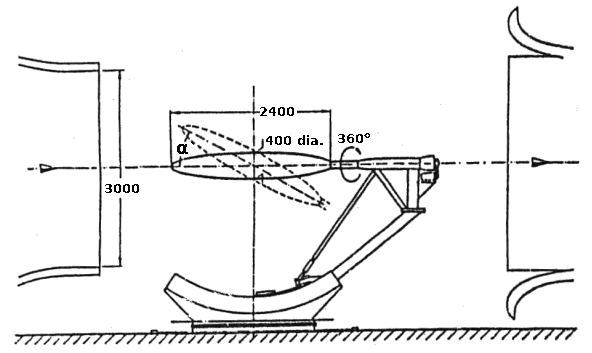
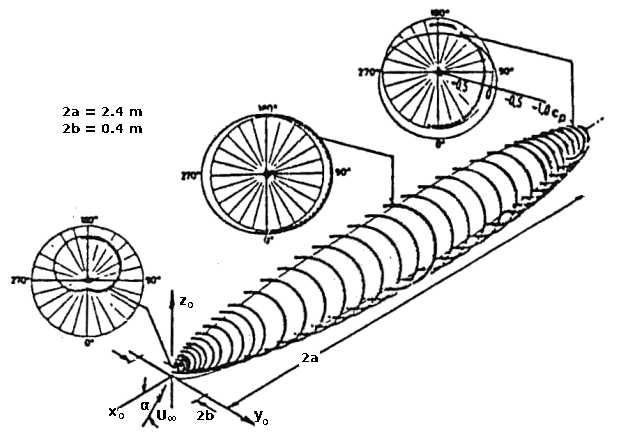
The wind tunnel model consists of a 6:1 prolate spheroid, as shown in figure 1 and figure 2.
Several incidence/Reynolds number combinations have been investigated, and data about transition in the 3d boundary layer, development of the boundary layers, 3d boundary layer separation and the separated flow field have been obtained. Measured data are surface pressures, skin friction, and mean velocities in the boundary layer and in the flow field.
 Fig. 1: Prolate spheroid model in th DLR 3x3m low speed wind tunnel. (Dimensions in mm)
 Fig. 2: Prolate spheroid geometry and typical surface pressure distributions
Details of Model
The experimental investigations on the flow around the inclined prolate spheroid were carried out in the 3 m Low Speed Wind Tunnel NWG at DLR Göttingen and in the pressurised low speed tunnel F1 of ONERA. Both prolate spheroid models were made using the same mould, thus shape and size of the models was identical.
Reynolds numbers and angle of inclination \(\alpha\) are given in the table below.
| Angle \(\alpha\) | Re | |
|---|---|---|
| NWG-10 | \(10^o\) | \(7.7\times 10^6\) |
| NWD-30 | \(30^o\) | \(6.5\times 10^6\) |
| F1-30 | \(30^o\) | \(40\times 10^6\) |
General Geometric Arrangement: Body of Revolution
- Body data: 6:1 prolate spheroid with a length of \(L= 2.4\) m and major half axes of 0.2 m.
- Geometric definition: The model shape is described analytically. The co-ordinates are design values. Contour deviations are less than 0.25% of the maximum diameter.
- Model support: The model was mounted on a central rear sting. The outer diameter of the sting was 110 mm. The model could be turned around its longitudinal axis through \(\phi = 0^o\) to \(360^o\), thus allowing the flow in one cross-section to be measured with one probe/sensor fixed to the model.
Experimental Details
General Tunnel Information
Measurements with the prolate spheroid models at angle of incidence have been performed in two different wind tunnels. These are the 3 m Low Speed Wind Tunnel of DLR,Göttingen (A) and the F1 Wind Tunnel of ONERA, Le Fauga (B).
Tunnel A
- Tunnel designation: 3 m Low Speed Wind Tunnel, Göttingen (NWG).
- Tunnel characteristics: Low speed wind tunnel, Göttingen type with closed return and open test section, nozzle contraction 5.4, Speed range: 0 - 65 m/s, continuously running.
- Test section: Test section dimensions: 3 m wide, 3 m high and 6 m long, open jet.
Free stream conditions
- Determination of free stream conditions: The total pressure is determined from the wall pressure in the settling chamber. As the tunnel has an open (free jet) test section the ambient, atmospheric pressure is taken as the static pressure. The dynamic pressure in the test section is calculated from the settling chamber pressure using a correction factor determined from a tunnel calibration. The (total) temperature is measured in the collector and assumed to be constant in the tunnel.
- Tunnel calibration: Spot checks of calibrations have been performed from time to time.
Flow quality
- Flow uniformity: The deviations of the dynamic pressure are less than +/-0.5% at the standard position of the models. At distances from the nozzle exit between 1 m and 4 m the maximum deviation of the static pressure is +/-1.5% of the dynamic pressure. The flow angularity on the test section centreline is constant within +/-0.25o in the vertical plane, as measured by a multihole pressure probe.
- Temperature variation: As the tunnel has no cooler, the temperature cannot be controlled. This means that the temperature in the tunnel increases during each run. The temperature increase with time is dependent on the velocity and on the ambient temperature. It was tried to keep the Reynolds number constant by manual control of the fan speed. Temperature variations in the tunnel circuit are assumed to be small and therefore are neglected.
- Flow unsteadiness: The overall turbulence level is rather high compared to other wind tunnels. Values of 0.33% to 0.4% for the streamwise velocity fluctuations and about 0.8% for the vertical and spanwise components have been measured.
Tunnel B
- Tunnel designation: F1 Wind Tunnel (F1).
- Tunnel characteristics: Pressurised low speed wind tunnel, closed test section, nozzle contraction ratio 7.2, Maximum pressure: 4 bar, Maximum speed: 125 m/s at 1 bar, 80 m/s at 4 bar, continuously running.
- Test section: Closed test section, Test section dimensions: 4.5 m wide, 3.5 m high and 10 m long. A slight divergence of the two vertical test section walls compensates the boundary layers along the walls to ensure a flow without longitudinal gradients.
Free stream conditions
- Determination of free stream conditions: Several Prandtl antennas placed in the upstream part of the test section, wall pressure taps at the end of the contraction and a Pitot probe in the settling chamber are used for the determination of the reference static, total and dynamic pressures. The (total) temperature is measured in the settling chamber and assumed to be constant in the tunnel.
- Tunnel calibration: The tunnel has been calibrated after construction.
Flow quality
- Flow uniformity: The longitudinal gradient of static pressure or Mach number is negligible. The flow angularity in the test section is zero, with an inaccuracy of +/-0.2o. The stagnation pressure shows almost perfect uniformity. The wind tunnel is supplied with compressed air generated by a centrifugal compressor through a buffer tank. The tank is used in combination with a servocontrol for regulating the pressure around an assigned value. The relative deviations of the stagnation pressure are smaller than +/-10-3.
- Temperature variation: A water cooler is used to stabilise the stagnation temperature around an assigned value between atmospheric temperature and 40oC. A servo-control maintains this temperature around the assigned value within better than 1oC.
- Flow unsteadiness: Hot wire measurements in the test section showed a low streamwise turbulence level smaller than 0.1%. For Mach numbers above 0.2 the noise level is less than 0.01 in terms of \(c_p\)-RMS if the RMS pressure fluctuations are normalised by the dynamic pressure in the free stream.
Model Pressure Measurements
The prolate spheroid model is equipped with 42 pressure taps of 0.3 mm diameter positioned on one meridian in non-equidistant distances. Due to the fact that the model could be rotated around its longitudinal axis the wall pressures could be measured at the 42 cross sections with a high resolution in the circumferential direction.
Boundary Layer Measurements
Mean velocity profiles in the three-dimensional boundary layers have been measured for a model angle of incidence \(\alpha =10^o\) applying pressure probes. The probe, with its traversing mechanism inside the model, could be positioned in four cross sections. The probe was traversed normal to the model surface. A three-hole-direction-probe was used to determine the longitudinal and spanwise velocity components \(U\) and \(V\). The static pressure used in the data reduction was measured at the wall and assumed to be constant through the entire boundary layer thickness. Errors could have been introduced here, if thick boundary layers close to separation were investigated.
Flow Field Measurements
Mean velocities in the flow field around the model were measured with pressure probes in both wind tunnels. A 10-hole probe was used in the NWG tunnel, and a five-hole probe in the F1 tunnel.
The ONERA five-hole probe, with a diameter of 3 mm, was also traversed on rays perpendicular to the model surface.
Data Accuracy
Estimated accuracy of Free stream conditions:
| Flow velocity | +/-0.25% NWG |
| Dynamic pressure | +/-0.3% F1 |
| Model incidence | +/-0.1o |
Measured data:
| Pressure coefficients: | \(\Delta c_p = \pm 0.01\) (NWG, \(U_{\infty} = 55\) m/s) |
| \(\Delta c_p = \pm 0.005\) (F1, \(U_{\infty} = 75\) m/s, \(p_o = 4\) bar) | |
| Wall shear stress: | \(\Delta c_f/c_f = \pm 0.1\) |
| \(\Delta \gamma_w/\gamma_w = \pm 0.1\) | |
| Velocity: | \(\Delta U_{\gamma}/U_{\gamma\beta} = \pm 0.01\) |
| \(\Delta \gamma < 1^o\) |
Available Measurements
The data available includes:
- Skin friction coefficient distribution around the body at several different streamwise \(x\) locations
- Surface pressure coefficient distribution along the length of the body at a number of circumferential angles
- Profiles of mean \(U\) and \(V\) velocities at a number of streamwise locations and circumferential angles.
No corrections were applied to the data. As the boundary conditions are known (free jet in NWG, straight solid wall in F1), conventional corrections are possible. Solid blockage effects are estimated to be \(\Delta U_{\infty}/U_{\infty} = -0.003\) at \(\alpha =10^o\) and \(-0.01\) at \(\alpha= 30^o\) for the NWG tunnel and to be \(\Delta U_{\infty}/U_{\infty} = 0.018\) at \(\alpha = 30^o\) for the F1 one. Lift interference effects are estimated to be \(\Delta \alpha = 0.3^o\) in NWG and \(0.2^o\) in Fl at \(\alpha = 30^o\). They are negligible at \(\alpha = 10^o\).
Sample plots of selected quantities are available.
The data can be downloaded as compressed archives from the links below, or as individual files.
The file readme.txt contains some description of the files and cases.
Pressure Coefficients
| F1-30 | NWG-10 | NWG-30 |
|---|---|---|
| f1_30_cp.dat | nwg10_cp.dat | nwg30_cp.dat |
Skin Friction Coefficients
| F1 Case | NWG Cases | ||||
|---|---|---|---|---|---|
| \(x/(2a)\) | F1-30 | \(x/(2a)\) | NWG-10 | NWG-30 | |
| 0.056 | f1_30_cf_01.dat | 0.053 | nwg10_cf_01.dat | nwg30_cf_01.dat | |
| 0.143 | f1_30_cf_02.dat | 0.139 | nwg10_cf_02.dat | nwg30_cf_02.dat | |
| 0.228 | f1_30_cf_03.dat | 0.223 | nwg10_cf_03.dat | nwg30_cf_03.dat | |
| 0.315 | f1_30_cf_04.dat | 0.309 | nwg10_cf_04.dat | nwg30_cf_04.dat | |
| 0.401 | f1_30_cf_05.dat | 0.395 | nwg10_cf_05.dat | nwg30_cf_05.dat | |
| 0.571 | f1_30_cf_06.dat | 0.480 | nwg10_cf_06.dat | nwg30_cf_06.dat | |
| 0.658 | f1_30_cf_07.dat | 0.565 | nwg10_cf_07.dat | nwg30_cf_07.dat | |
| 0.741 | f1_30_cf_08.dat | 0.652 | nwg10_cf_08.dat | nwg30_cf_08.dat | |
| 0.828 | f1_30_cf_09.dat | 0.738 | nwg10_cf_09.dat | nwg30_cf_09.dat | |
| 0.878 | f1_30_cf_10.dat | 0.825 | nwg10_cf_10.dat | nwg30_cf_10.dat | |
| 0.947 | f1_30_cf_11.dat | 0.883 | nwg10_cf_11.dat | nwg30_cf_11.dat | |
| 0.936 | nwg10_cf_12.dat | nwg30_cf_12.dat | |||
Velocity Profiles
| F1-30 Case | |||
|---|---|---|---|
| \(\phi\) [o] | \(x/(2a)=0.527\) | \(x/(2a)=0.7\) | \(x/(2a)=0.917\) |
| 100 | f1_30uff_01.dat | f1_30uff_15.dat | f1_30uff_29.dat |
| 110 | f1_30uff_02.dat | f1_30uff_16.dat | f1_30uff_30.dat |
| 120 | f1_30uff_03.dat | f1_30uff_17.dat | f1_30uff_31.dat |
| 130 | f1_30uff_04.dat | f1_30uff_18.dat | f1_30uff_32.dat |
| 135 | f1_30uff_05.dat | f1_30uff_19.dat | f1_30uff_33.dat |
| 140 | f1_30uff_06.dat | f1_30uff_20.dat | f1_30uff_34.dat |
| 145 | f1_30uff_07.dat | f1_30uff_21.dat | f1_30uff_35.dat |
| 150 | f1_30uff_08.dat | f1_30uff_22.dat | f1_30uff_36.dat |
| 155 | f1_30uff_09.dat | f1_30uff_23.dat | f1_30uff_37.dat |
| 160 | f1_30uff_10.dat | f1_30uff_24.dat | f1_30uff_38.dat |
| 165 | f1_30uff_11.dat | f1_30uff_25.dat | f1_30uff_39.dat |
| 170 | f1_30uff_12.dat | f1_30uff_26.dat | f1_30uff_40.dat |
| 175 | f1_30uff_13.dat | f1_30uff_27.dat | f1_30uff_41.dat |
| 180 | f1_30uff_14.dat | f1_30uff_28.dat | f1_30uff_42.dat |
References
- Kreplin, H.P. (1995). Three-dimensional boundary layer and flow field data of an inclined prolate spheroid. AGARD FDP WG-14 Experimental test cases for CFD validation, Test Case ID: GE-20.
Indexed data:
| case074 (dbcase, flow_around_body) | |
|---|---|
| case | 074 |
| title | Flow around inclined prolate spheroid |
| author | Kreplin |
| year | 1993 |
| type | EXP |
| flow_tag | 3d, separated, bluff_body |