Vortices in Boundary Layer
Experiments by Pauley and Eaton
Description
Flow over an initially two-dimensional turbulent boundary layer with longitudinal embedded vortices. 3D flow with constant temperature.
Geometry of the Computational Domain
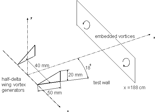
At \(x = 0\), two half-delta-wing generators, 20 mm high and 50 mm long, are mounted at an angle of attack on a flat plate called the “test wall”. They are set up symmetrically on each side of the test wall centreline so that the spacing between the midway point of the delta wing chord of the generators is 40 mm. The angle of attack between the chord and the tunnel centreline is 18o, as shown in figure 1.
The boundary layer is tripped 53 cm upstream of the vortex generators, and the flat plate extends far enough downstream (to \(x=200cm\)) in order to accommodate the region located at \(x = 188\) cm (\(0.16 < y < 6.75\) cm and \(0 \le z \le 15\) cm) where the furthest downstream measurements are provided.
Flow Characteristics
A pair of strong longitudinal vortices and arrays of weaker longitudinal vortices are both embedded in an otherwise two-dimensional turbulent boundary layer. The vortices remain close to the wall producing significant levels of spanwise skin friction and, consequently, a greater rate of streamwise circulation decrease.
Flow Parameters
Air at standard conditions.
Nominal free-stream velocity: \(U_e = 16\) m/s (at the edge of the boundary layer).
Inflow Conditions
In the undisturbed case, without the presence of the vortex generators, the flow is two-dimensional and the boundary layer has the following features at \(x=0\) (the boundary layer is tripped at \(x = -53\) cm):
| Boundary-layer thickness | 13 mm |
|---|---|
| Momentum thickness Reynolds number | \(Re = 1700\) |
| Free-stream turbulence level | 0.2% |
For those performing simulations, an appropriate strategy could be to run a separate developing boundary layer case in order to match these conditions, and use profiles from that as inlet conditions at a suitable distance upstream of the vortex generators.
Experimental Details
Velocity measurements using a miniature five-hole pressure probe whose tip is 2.7 mm in diameter with 0.4 mm pressure ports. Streamwise and spanwise components of the skin friction measured using a dual sublayer fence probe.
Measurement Errors
Mean flow measurements:
| \(\delta(\text{flow angles})\) | \(\pm 0.5^o\) |
| \(\delta(\text{velocity vector magnitudes})\) | \(\pm 5\%\) |
Available Measurements
At two \(x\) positions (\(x=97\) and \(188\) cm) the following measurements are provided:
Contour maps of:
- First order moments: \(U/U_e\), \(V/U_e\), \(W/U_e\)
- Second order moments: \(\overline{u^2}/U_e^2\), \(\overline{v^2}/U_e^2\), \(\overline{w^2}/U_e^2\), \(\overline{uv}/U_e^2\), \(\overline{uw}/U_e^2\), \(\overline{vw}/U_e^2\)
- Third order moments: \(\overline{uuu}/U_e^3\), \(\overline{vvv}/U_e^3\), \(\overline{www}/U_e^3\), \(\overline{uuv}/U_e^3\), \(\overline{uuw}/U_e^3\), \(\overline{uvv}/U_e^3\), \(\overline{uww}/U_e^3\), \(\overline{vvw}/U_e^3\), \(\overline{vww}/U_e^3\), \(\overline{uvw}/U_e^3\)
Available \(x\) stations:
| \(x\) position | \(y\) range | \(z\) range | filenames |
|---|---|---|---|
| \(x = 97\) cm | \(0.16 < y < 5.25\) cm | \(0 \le z \le 12\) cm | 3#fcna.dat |
| \(x = 188\) cm | \(0.16 < y < 6.75\) cm | \(0 \le z \le 15\) cm | 9#fcna.dat |
The data can be downloaded as compressed archives from the links below, or as individual files.
Sample plots of selected quantities are available.
| \(x=97\) cm | \(x=188\) cm | |||
|---|---|---|---|---|
| \(z\) [cm] | File | \(z\) [cm] | File | |
| 0.0 | 3afcna.dat | 0.0 | 9afcna.dat | |
| 0.5 | 3bfcna.dat | 1.0 | 9bfcna.dat | |
| 1.0 | 3cfcna.dat | 2.0 | 9cfcna.dat | |
| 1.5 | 3dfcna.dat | 3.0 | 9dfcna.dat | |
| 2.0 | 3efcna.dat | 4.0 | 9efcna.dat | |
| 2.5 | 3ffcna.dat | 5.0 | 9ffcna.dat | |
| 3.0 | 3gfcna.dat | 5.5 | 9gfcna.dat | |
| 3.5 | 3hfcna.dat | 6.0 | 9hfcna.dat | |
| 4.0 | 3ifcna.dat | 6.5 | 9ifcna.dat | |
| 4.5 | 3jfcna.dat | 7.0 | 9jfcna.dat | |
| 5.0 | 3kfcna.dat | 7.5 | 9kfcna.dat | |
| 5.5 | 3lfcna.dat | 8.0 | 9lfcna.dat | |
| 5.0 | 3mfcna.dat | 8.5 | 9mfcna.dat | |
| 6.5 | 3nfcna.dat | 9.0 | 9nfcna.dat | |
| 7.0 | 3ofcna.dat | 9.5 | 9ofcna.dat | |
| 7.5 | 3pfcna.dat | 10.0 | 9pfcna.dat | |
| 8.0 | 3qfcna.dat | 10.5 | 9qfcna.dat | |
| 8.5 | 3rfcna.dat | 11.0 | 9rfcna.dat | |
| 9.0 | 3sfcna.dat | 11.5 | 9sfcna.dat | |
| 9.5 | 3tfcna.dat | 12.0 | 9tfcna.dat | |
| 10.0 | 3ufcna.dat | 13.0 | 9ufcna.dat | |
| 10.5 | 3vfcna.dat | 14.0 | 9vfcna.dat | |
| 11.0 | 3wfcna.dat | 15.0 | 9wfcna.dat | |
| 11.5 | 3xfcna.dat | |||
| 12.0 | 3yfcna.dat | |||
Main References
- Pauley, W.R., Eaton, J.K. (1988). Experimental study of the development of longitudinal vortex pairs embedded in a turbulent boundary layer. AIAA J., Vol. 26, p. 816.
- Pauley, W.R., Eaton, J.K. (1989). Boundary layer turbulence structure in the presence of embedded streamwise vortex pairs. Proc. 7th Int. Symp. on Turbulent Shear Flows, Stanford Univ.
Indexed data:
| case012 (dbcase, semi_confined_flow) | |
|---|---|
| case | 012 |
| title | Vortices in Boundary Layer |
| author | Pauley, Eaton |
| year | 1987 |
| type | EXP |
| flow_tag | 3d, 3dbl |
